What you will find here: Intended to display minor modifications to my Westfield SEi, this blog now witnesses the two year rebuild (and more) after a major crash in October 2011. Have fun and feel free to add a comment at the end of any post.
Best viewed with Firefox

Pages

Thursday, January 31, 2013

Centre console ready

With the fuel issues solved and a first test run, I can go on with the wiring ...
The centre console will be bolt between the transmission tunnel and the dashboard. For easy access, it can be removed, the electrical connection is realized with multi-pin connectors. An old power supply helped to check the wiring.
Cheers.

Sunday, January 20, 2013

Kent Injection

The Jenvey fuel rails are connected with an aluminium tube, sealed by O-ring on each side. Not a happy setup if you ask me. I prefer a screwed connection, that's why I ordered fuel rails with Dash 06 connections each side...
... which made me run into the next problem: the connectors are too close to screw in a coupler. I had to cut two steel connectors and weld them back to back. This is not the final version of the fuel rail. The definite version will be of one piece, but it will be manufactured later.
With the fuel plumbing all done and ready, the ECU repaired and connected, I finally was able to start the engine.
Cheers.

Monday, January 14, 2013

Fuel issues

Emerald confirmed one of the injector drivers being fried, for whatever reason. Repair is done under warranty, although this ECU has more than two years. Talk about customer care! Just great!
With the ECU abroad I had time to have a look at the fuel plumbing and noticed a very small leak where the pre-pump filter meats the high pressure pump. Diameter is reduced from 15mm to 12mm and at the time, I hadn't found the best solution for plumbing this in. Everything is dismantled and I will chase the right tube and clips to do it right.
When I unmounted the fuel pump, I found out that a harness without connectors might be light and have less points of failure, but it is difficult to quickly unmount a device. Saturday was soldering day, the pump got a connector. And I started to wire the fuse/relay-box.
Cheers.

Sunday, January 6, 2013

Injection trouble

Ideally, the engine would have started with the injectors plumbed in and connected. My son had the privilege to fill the tank. Unfortunately, injectors 2 and 3 sprayed even with the engine stopped. I didn't see it and cranked the engine, which means it went full of unburnt fuel without starting. First I doubted the injectors, then I assembled everything with the injectors hanging loose ... only to find out that the injectors are ok (swapped the connectors, swapped the injectors, checked and double-checked the harness).
The injectors spray away from the engine bay and I can watch what happens, measure the harness resistance, check the pins, read the voltage a.s.o. I sent all the data and the map to Dave and Karl at Emerald and hope they can help.
With the engine full of fuel, there are some things to do prior to start the engine again (or try to). My method was to unmount the exhaust and with the help of some hose and tissue catch the fuel that already had been spit out. Then I put out  the sparkplugs and cranked the engine (without ignition!!!) ... which means fuel spraying all over the place! What a mess! Even with lots of tissue around, it's very impressive to see how high and far it sprays. After this, more fuel catched in the exhaust. 
For the next tests it will be ok, but before I start the engine for good, I will also change the oil which is contaminated with fuel as well. Now I have to wait for an answer from the ECU manufacturer.
Cheers.

Monday, December 31, 2012

Fuel sensor

The Stack fuel gauge is fully programmable. You can connect whatever sensor and chose from different backlight colors for maximum, minimum or normal operation. The sensor is quite an old one but still works fine. Settings for the Stack fuel gauge are customized, min and max levels can be programmed individually.
Dash cabling is almost finished. The rest is for next year ... Happy New Year! See you in 2013!
Cheers.

Friday, December 28, 2012

Dash cabling

No scuttle yet means free access to the rear side of the dashboard. Switchwork of starter, horn, high beam and the oil pressure gauge with it's low pressure warning light are done.
It's a start and there is more to come. To test the cabling, I crimped some provisional terminals and connected them to the battery. Nothing is more frustrating then short circuits during installation, and with some good connectors and a little discipline, this can be evitated.
Cheers.

Wednesday, December 26, 2012

Fuel plumbing - done

The throttle bodies are of DHLA-type, which means two separate double housings. Today I cut the link for both fuel rails and inserted it. The housings are also mechanically linked to operate the throttle and I had to cut the lever to suit my installation. The right housing is at the front of the car where the fuel will enter the fuel rail. Throttle position sensor unmounted from the Dellortos and mounted to the Jenvey throttle bodies ... the principle remains the same, but the TPS has to be recalibrated with the Emerald ECU.
Fuel goes through the rails and is feeded to the injectors, excessive fuel comes out at the end of the rail and goes back to the swirl pot. In between there is the fuel pressure regulator that will be set to 3bar. The FPR is plumbed in and was the last item of a long list. Hopefully fuel plumbing is done now. The check list is rather long with a lot of connections from the tank to the injectors and back.
Cheers.

Tuesday, December 25, 2012

Fuel pressure regulator

Studs had all different lengths and were too long for the throttle bodies anyway, which took me an hour to measure, cut and mount them with some thread compound.
Fabricated a bracket to mount the fuel pressure regulator near the fuel rail and swirl pot. This gives a nice ensemble of everything around the fuel. And a good reason to try that bender I recently bought from a friend. The bracket is out of 5mm aluminium and is fixed between two chassis rails.
Cheers.

Monday, December 24, 2012

Injectors

There is no color code conspiration. Although I was after it and almost cracked the enigma, there is none. Maybe for some manufacturer, but even there you find remarks like "color may differ from picture" a.s.o. What you must know to identify an injector is the part-number and manufacturer, then you can search for the flow-rate, resistance and all relevant data. Unless somebody already made all the the work for you, like Stan Weiss for example. Have a look at his site here. I downloaded the list and made it available as a .pdf.
To get an approximate flow rate for a 4 cylinder engine, multiply the injector rate in cc/min by the number of injectors and then divide the answer by five. In this example: 272cc/min x 4 = 1088cc/min total available flow. Divide by five gives you 217.6 bhp. That is with the injector 100% flat out at a fuel pressure of 3 bar.  Normally you aim for 80% of total duration making the 272 injectors worth about 175 bhp at 3 bar pressure for my engine. That would be a rather optimistic calculation and my engine will not achieve that amount of power. This is not an exact calculation because it doesn't take in account other parts of the engine responsible for the power output (camshaft, valves, pistons ...).
Oh, and yes, by the way ... mine are pink !
Cheers.

Goodbye carbs

... welcome injection!
Jenvey DHLA style throttle bodies + fuel rails + injectors, trial fit for measurements.
New inlet manifold gasket is inside this kit from Burton. I mounted it with some silicon paste and also sealed the bolt in the middle which plugs a water gallery.
This throttle link commanded the Dellortos but should also be quite practical to link the throttle bodies with the throttle pedal. It's a bolt-on, so if this doesn't suit, I can take it of.
Cheers.

Wednesday, December 19, 2012

Engine runs

Some preparation work prior to first run after 14 months included the build of a launching device. This is the result and comprises a jerrycan, a battery, some switchwork (toggle for ignition, pump, ECU and charge, charging light, starter push-button) and an oil pressure gauge.

The diagram shows what is needed to start an engine. The sensors have to be connected to the ECU and the first start wasn't successfull due to an error in the crank sensor wiring. Polarity is relevant for that sensor and information is somehow spread over different documents, that's why I composed that little pic to collect all the info in one place.
After a lot of work, the engine finally runs and I was proud to call the kids and give some good kicks to the throttle so they can hear it over the phone.
Cheers.

Monday, December 17, 2012

Coolant fill

The new radiator also meant that most of the coolant was lost during the crash and the change. Without the scuttle where the nice aluminium expansion tank is fixed, I mounted the old one on top of the engine and filled the circuit via the thermostat housing. Once the liquid spills out of the small radiator port, it has to be closed, then the thermostat housing is filled to level and also closed. The expansion tank is then filled a little above minimum and closed. Time to look around the whole circuit for leaks. When the engine gets started and the coolant circuit is under pressure, there might appear some drops on connections and it will be fixed. For now it's good to know that the coolant is in again. One more step done before restart.
Cheers.

Saturday, December 15, 2012

Launch facility


A year and two months since the engine ran, some more preps done before I can push the button. Carbs are on again, HT (high tension) leads connect the ignition coils to the spark plugs, throttle pot newly calibrated.
Before converting to injection, I want to start the engine on carbs. The tank and fuel pipes have not been tested, neither the pumps. That's why I built this launch facility on a trolley. The switchboard has an ignition switch and a start button, the pump, filter and fuel pressure regulator are from the old installation. Once the engine coolant has been filled, the battery and switchboard get connected to the ECU and starter already installed in the car. This provisional starting solution permits to test if the engine runs and if the new oilpump builds enough pressure, after which I will check all the rest before mounting the throttle bodies.
Cheers.

Tuesday, December 11, 2012

ECU alive

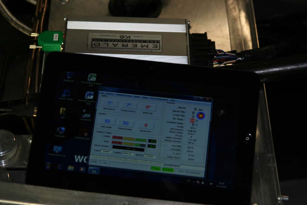
After more than a year without current, it was time to check the ECU. The newly acquired Windows7 tablet has the Emerald software installed, the driver for the serial-to-USB converter has been updated. The connection worked first try, although I couldn't check everything without a running engine. But one thing I know for sure now, the temp sensor showed only 5°C in the workshop and that's bloody cold!
Cheers.