What you will find here: Intended to display minor modifications to my Westfield SEi, this blog now witnesses the two year rebuild (and more) after a major crash in October 2011. Have fun and feel free to add a comment at the end of any post.
Best viewed with Firefox

Pages

Thursday, March 22, 2012

Size matters

Long versus short. The clutch cable in the car was rather long. The short one is from a Ford Escort MkII and will be a better fit. In case you encountered a similar problem, try to get the clutch cable with the Ford part# 15613600 from a 75-80 Ford Escort (talking about the 20th century!).
 
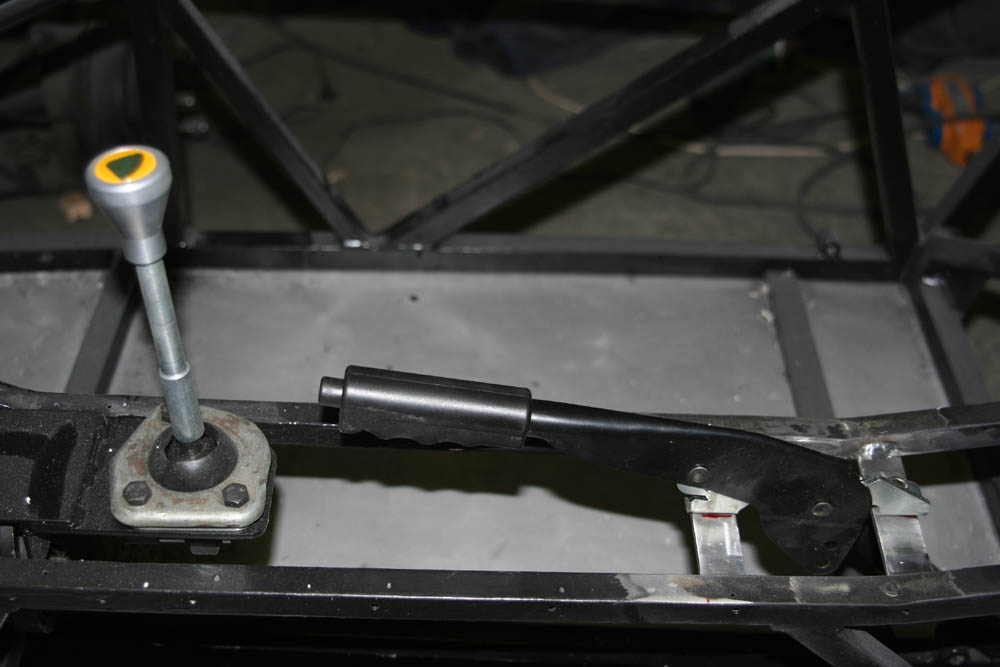
The handbrake lever positioned further back will not interfere with the gearlever anymore. I'm quite pleased with this disposition. Hopefully, I will find a good way to clothe both levers and make it look like a well designed car from the inside as well.
Cheers.

Wednesday, March 21, 2012

Always work and no play makes Jack ...

24th Techno-Classica Essen / Germany  from 21st to 25th March 2012.
THE exhibition not to be missed if you're a fan of classic automobiles.
I'll be there on Friday 23rd to buy some stuff for my car and admire all those fantastic cars, motorcycles and accessories. It's an overwhelming fair both in extent and in quality.
Cheers.

Monday, March 19, 2012

The never ending change

Yeah, tonight I want to put the new handbrake lever into the car ... well, that's what I thought. After I put the gearlever with it's extension, it became obvious that they interfere.
Before cutting, welding and painting once again, this time to reposition the handbrake lever, I allowed myself for some trial seating to check for the new gearlever position. Perfect! Later I will cut the lever to the most practical length. The extension works fine, but I have to check for the reverse protection.
The well known history ... I already cut out the old brackets, prepared some steel and marked the chassis. Welding is next, then drilling and painting the altered chassis section. Recurring gestures.
Cheers.

Water cooling circuit

As assembly progresses (well, sort of), some theory worse to be spread about the plumbing. Let's start with the water cooling circuit. Starting with a layout lent in a german forum, I adapted it to what will be found in my car once completed (ex the water temperature gauge which will be integrated into the digital Stack dash). Quite a basic setup without a heater, hence the missing pipes and valves. Note the two separate temperature sensors, one for the stack gauge and one for the Emerald ECU. There are two ways to switch the fan once a set temperature has been reached:
1) via the temperature switch (mechanical / bi-metal) in the thermostat housing, fixed value
or
2) via the ECU where the switching temperature can be set as wished.
Cheers.

Saturday, March 17, 2012

... and more brackets!

A rebuild is a chance to do things better. One annoying missing feature was a rest-pedal for the clutch foot during long journeys. Out of aftermarket aluminium pedals I cut two small pedals and mounted the larger one. If it appears to be too large, I will mount the smaller one. A small bracket welded to the chassis holds the pedal.
The high pressure pump for the fuel injection conversion will be mounted near the swirlpot and underneath the throttle-bodies. A little bit of steel is needed to fabricate a bespoke bracket.
 Bracket welded in place and holding the HP pump for trial fit.
Top view to show how the HP pump will connect to the swirlpot. The pump will almost not be visible once the throttle-bodies are in mounted.
Cheers.

Sunday, March 11, 2012

Swirlpot

The fuel injection system will need a swirl pot. But where to put it in such a small car? After a first attempt to install everything in the boot, the rebuild allows for some other ideas. Starting with the purpose built bracket early this Sunday morning ...
... and the swirlpot mounted. Now the ideal spot for the high pressure fuel pump can be found and another steel bracket will be welded to the frame as this device is quite heavy.
A little bit of theory about the plumbing of a swirlpot in a fuel injection system from SBD. Modern fuel injected cars have the swirlpot integrated in the tank. In a car originally not equipped with EFI, a swirlpot has to be fitted separately to avoid fuel failure due to surge in fast corners.
Cheers.

Thursday, March 8, 2012

Pedalcar

The clutch cable routing shows that the cable is quite long. Connecting it to the pedal is not complicated and there is enough remaining cable for adjustment. I wanted to keep the clutch cable operated and not add a piston and convert to hydraulic.
The pedals mounted with the throttle operation finished, the clutch pedal to be adjusted and the brake pedal to be modified. I decided to alter the original adjustment system for ease of use. With all three pedals in place, it is possible to choose a spot for the footrest destined for the clutch-foot. Not much room left, but I really want to try fitting one for comfort during long journeys.
Cheers.

Monday, March 5, 2012

Cleckos

Funny name. Another one could have been "provisory rivets". This would have explained the function as well. A spring loaded inner mechanism expands with the special tool pictured. Then the clecko is fixed and the spring released.
One pic instead of thousand words, a few cleckos help to provisorily fix the panel. Than I can mark the big holes for the brake master cylinders and cut them out.
As soon as the panel is fixed, the brake master cylinders can be mounted. For good.
Backside of the pedalbox prior to mount the pedals. Throttle and brake linkage are solved, a solution for the clutch activation has to be invented yet. But this is basic mechanics and feasable (hopefully...).
Cheers.

Thursday, March 1, 2012

Repro

Not the best workshop session tonight because I'm not completely satisfied with my work. Half way through, it became obvious that the reproduced new panel will not enter the frame with the engine already mounted. Two possibilities:
#1 engine out - panel in - engine in
#2 cutting the panel into two pieces
As it will almost not be visible, I opted for solution #2. It would have been nice to have that panel in one piece, but the amount of work would have been immense. Heat shield will cover the cut.
Split panel in place with Sicaflex for sealing and fixing, 4x12mm rivets with large heads. Imagine some heat shield on it and the swirl pot fuel tank mounted. A.s.a.p. I will add a pic with the panel in focus.
Cheers.

Sunday, February 26, 2012

Gearlever

Different solutions for one problem... This mod is often made to the gearlever to put it further away from the dashboard. The lever is simply cut and then welded with an angle piece.
As shown earlier, a gearlever extension is now available. There is no need for an angled gearlever anymore.
The original complete gearlever is quite expensive, but the upper part is available separately. After some drilling and threading, it's done. The final assembly and adaptation will be made directly in the car.
Cheers.

Saturday, February 25, 2012

Substitute

To cut out a chassis rail is one thing, to replace it is something else. The photo shows the replacement not too far away from the original location. All in all, the chassis will keep it's initial strength.
This pic is for memory only and to show the mechanical odometer drive. Once all the panels in place, it will be hidden. As speed will be measured electronically, the mechanical drive will not be connected (note shiny new paint after grinding and welding!).
Latest order placed at Burton (GB), the new Pace DSP5 competition oil pump for wet sump. With a 20% higher volume and integrated sandwich plate, it's a piece of clever engineering to replace the setup currently used. I'm even tempted to try it out without the oil cooler to save weight. The higher volume might suffice to keep the oil temperature low.
Cheers.

Wednesday, February 22, 2012

Back in

One hour work with Max and Pit and the engine together with the gearbox is back in the chassis (... and always amazing how much crap lying around I discover when checking the pics :-).
This is the original place for the gearlever. To put it further back in a Seven (thus avoiding the gearlever to touch the dashboard in first, third and fifth gear), you can throw in a gear lever extension. In this case and with a X-flow engine coupled to a T9 gearbox, one of the chassis rails is in the way.
Two cuts later and the rail is out of the way. Later I will weld a similar rail at a different place to ensure stability of the frame. In this case, the place is not crucial.
The extension put in place for trial fit.
And one more for today showing the oil-fill-in of the gearbox, once for memory and once for other web users. This is an often asked question how to check the level and refill. It's the square drive screw and when the inner panels are mounted, it will not be accessible anymore. As we spilled some oil when manipulating the gearbox, we have to fill to the required level before putting the panel in place. I may add a trap in this place to allow access later on.
Cheers.

Monday, February 20, 2012

Floored

Sicaflex is applied both for strength and sealing before the aluminium panels get fixed to the frame. Sicaflex is sticky and stains like shit, but apparently is one of the best adhesives available.
This time it's for good. The cleaned panels get fixed with 4mm aluminium rivets. You can see the riveter minutes before it was flying with lots of air time through the workshop. After only 32 rivets (yes I counted them out of deception) it broke down. The biggest annoyance is the loss of time when such a tool conks out, but ...
... it's replacement is such an über-riveter that I quickly forgot about it's five times higher price. Twenty minutes for panel #1 using the basic riveter, five minutes for panel #2 with the Ironside riveter. And one more very capable tool in the workshop! Stopping work and driving to the hardware store took me more than half an hour. Time easily saved during all the panel mounting that has to be done. I even found black rivets in that shop. They come handy to fix the inner (black!) panels.
Cheers.

Saturday, February 18, 2012

Riv'it

Some panels have to be redone, the old ones serve as model and help to try out the riveting tool.
The floor panels look really filthy and have to be cleaned from road dirt and oil. Dry with paper, then with white spirit, once more with paper and finally with Scotchbrite. The remaining Sicaflex must be grinded, I found no other way to get rid of it.
The chassis turned upside down and the cleaned floor panels put in place to check the fit. Sicaflex ready!
Next steps: applying the Sicaflex and fixing the panels per rivets.
Cheers.

Tuesday, February 14, 2012

Put the pedal to the metal

Amazingly enough how time flies... Those brake pipes take a lot of time to be bent. Although not completely happy with my work, it is a start. Once it is clear which flare has to be pressed, it's a matter of buying the right connectors and go on. This is only the front circuit with both brake master cylinders mounted provisorily. I'll decide later about a second try to make it look better, for now it's ok to locate all the different components of the brake circuit.
With the pedal box on the floor, the throttle activation must be re-engineered. After preparing the pedal mechanism to receive the clevis, an additional bracket performs as end stop for the Bowden cable. The cable arrives from the top and is pulled down by the pedal.
The nipple at the end of the Bowden cable is held by the clevis fixed to the pedal. All this has to move freely to evitate blocking or uneven pedal movement. That's why a lot of effort has been spent into designing this particular piece of kit.
Midday I will hop over to the braking workshop and buy some more stuff (connectors, half-nuts, a.s.o.) to continue work next weekend.
Cheers.

Monday, February 6, 2012

Brake pipe flaring

To achieve a perfect sealing of brake pipes, the ends have to be flared. Different standards are used and therefore, the aforementioned kit offers the possibility to manufacture different flares. First step is to cut the pipe to the desired length.
Even a well done cut should be deburred to avoid chips entering the pipe and block the fluid.
Then choose the right inserts by comparing with the pipe you want to reproduce. In this case, the pipe is 4.75mm and the flare is DIN.
The tool is assembled with everything needed to compress the copper/nickel pipe at it's end(s).
Pipe from the left stuck in the matrix, hydraulic screw with chosen punch, handle to turn, above grip to hold the tool by hand. There exist other flaring tools to be placed in a vice, this one has the advantage to be taken to the car. First try:
On the left compared to the old flare, on the right a different flare (double bubble) for trial.
Although this is no rocket science, I really have to warn everybody not owning the right skills or tools to let this work be done by professionals. I'm doing it on my own for the love of tools and the feeling to have achieved something by myself. If you're not sure, leave it to a specialized workshop.
Cheers.

Sunday, February 5, 2012

The LOFI principle

... or, why you have to put first into the chassis what you last took out. Clear? LOFI stands for: last out first in. Some of the brake lines mount easier with the engine out, so after a little attention with Scotchbrite, the first part of the brake system went in (T and RH brake line).
Where possible, I will re-use the old brake lines. For those not fitting in the new installation or in bad shape, I will replace them with new ones. To do this, you need a flaring tool kit and some special spanners (flare nut crowfoot wrench), new brake line and... keep those old lines, they are precious templates.
Mounting the pedalbox took me almost all the Saturday afternoon. The accelerator pedal mechanism is now ready to receive the clevis linking the bowden cable to the throttle.
This meant grinding and drilling to assure the clevis to move freely when activating the throttle pedal... which I hope doing a lot !!! After the mod I repainted the machined end with chassis paint.
Cheers.