What you will find here: Intended to display minor modifications to my Westfield SEi, this blog now witnesses the two year rebuild (and more) after a major crash in October 2011. Have fun and feel free to add a comment at the end of any post.
Best viewed with Firefox

Pages

Saturday, November 5, 2011

Striptease

Some more dismantling made today. Quite a progress, although it is obvious that reassembling will not be as easy. One has to get into the logics of the builder when stripping the car. The alloy panels are very thin and can easily be damaged. That's why I started with the left panel already bent beyond repair.
Rear view with the tank removed:
 Left side without panel, scuttle, windshield, exhaust and front suspension:
Without the panel, the damage to the frame is now visible:
View of bent front rail, not very visible in this pic, but in real it got quite some strain.
Next time I work on the car, I will start to strip the right front suspension and the rear axle. If possible, I try to leave us much parts assembled as possible when removing. Then the right alloy panel will be removed very carefully as it is almost not damaged. Just a slight bent where the flasher was mounted. The dashboard will follow and then the engine compartment.
Cheers.

Monday, October 31, 2011

"She will live"... well... hopefully !

Last Friday I got news from the insurance expert and although I haven't received the official report, the offer appears to be quite fair. The weekend was long enough to take a decision and I will (try to) rebuild my car. A box large enough in a storage depot half an hour away was booked and this morning, the ACL towing service transfered the car.
Arrival at it's temporary home.
Ready for dismantling.
Some of the bent parts after the first couple of hours.
From left to right, wheel carrier looks ok, lower shock absorber eye ripped off, lower pivot bent, upper wishbone and lower wishbone bent, on top bent steering column. Some more damaged parts still in the car.
The rest of the week I have to work abroad and will not be able to work on the car.
Cheers.

Sunday, October 23, 2011

Damage survey

The insurance company and the expert will probably forward a proposition next week. Today I took some more photos and I will start a list with the damaged items I already am sure to be replaced. Further on, I will have to look for a depot or big garage where I can dismantle the car. A specialized company will straighten the chassis, but therefore, it has to be completely naked.
Survey
Wishbone, upper and lower, if exactly the same is available, else the wishbones of both sides will be replaced. During dismantling, it will be visible if the wheel carrier and steering are damaged.
Nose, cracked beyond repair, brackets as well, nose pushed against bonnet during crash, damaged beyond repair as well. I'm not talking about smaller items like flasher or headlight a.s.o.
Radiator, damaged beyond repair, this was an original Caterham item.
 Nose pushed against bonnet, bonnet pushed against air-filter...
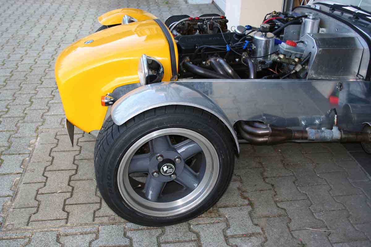
 Chassis tubes bent, upper, middle and lower on driver's side, some smaller tubes up front.
Where it all started for my car 23 years ago, Garage Jean Kesseler in Gonderange, Luxembourg. At that time this company was the Westfield importer for Luxembourg. Those not wanting to assemble the kit on their own bought it here OTR-ready (OTR - on the road).
Hopefully my car will be repaired during the winter months. As I found out by now, it has some history to be told, but I will only tell it when it is repaired and running again.
Cheers.

Monday, October 17, 2011

Journey's end


Pics speak for themselves...
Driver and passenger are ok, only minor injuries.
The driver coming from the other side turned left and didn't wait for me to pass by. Insurance has to decide whether the car will be repaired or written off. You may read less posts in the near future, but I hope to be back with better news soon.
Cheers.

Saturday, October 8, 2011

Autumn Seven


Couldn't resist and took some more beauty shots in this beautiful autumn scenery. Some last pics before the great switch from carbs to injection.
Cheers.

Monday, October 3, 2011

Speed sensor

Fantastic indian summer in Luxembourg... Lots of km done since Friday afternoon, and therefore, less work done on the car. 
A buddy in the french forum sevener.fr asked me how to mount the speed sensor for the Stack odometer. Here is a very simple method, a small aluminium piece fixed with the cycle wing bracket. This sensor is magnetic and counts the wheel nuts flying by (4 in this case). When setting up, the Stack asks for the wheel circumference and the number of events (bolts) per revolution, the electronics in the Stack can then calculate the speed the car is driving.
Cheers.

Tuesday, September 27, 2011

Wheelstuds

Annoying... Driving alone, there's no problem with the rear tires. The best part being to share this pleasure, I have to admit that the rear 225/45R15 are a little bit too large when taking along a passenger. Especially with the wheelspacers (25mm per side) I added when I ran the 195'ers. On some occasions, they rub in the wheel arches, mostly in right hand corners with the suspension completely compressed due to roadway damage. Yesterday I wanted to test how things work when I leave the spacers off but wrecked one of the wheel studs and/or the nut. Now I ordered some new spacers (15mm per side) and new longer studs and nuts. Those nuts are special items to mount Revolution rims (second from right in the pic). Originally, Westfield mounted two different lengths of studs (why?) but I will convert to equal length in the process. Hopefully all the goods will arrive before the weekend.
Cheers.

Tuesday, September 20, 2011

New vs. Old

Is there ever something "new"? I mean, really new never seen before complete new invention? I wonder. While preparing my car for a modern electronic fuel injection managed with an ECU, I surf the web to find similar installations for further inspiration how to do mine. And now I found this: an after-market mechanical fuel injection system for my car from the sixties !!! The firm producing it was Tecalemit. Even if it doesn't feature all the tweaks and features of modern technology, it has been there way ahead. Great ! Lucky me I didn't discover this before ordering the modern system, I might have been tempted... Some are offered now more or less complete from different engines, mostly race (formula sports, drag race, and they have been fitted to one of my all time favourite cars, the Ford GT40). Nowadays, people who restore historic race cars pay a lot of money to get one.
Cheers.

Monday, September 19, 2011

Beauty shot(s)

Always work and no play? Now and then I will post a beauty shot, mostly before or after a little run. I'm permanently looking for nice spots to picture the car, good light, interesting landscape, preferably some old industry or abandoned mill.
Cheers.

Bootlid

The rollbar has been modified to allow fitting an ancient suitcase. The outer tubes have moved further to the sides to free place. The bootlid must be modified accordingly. This is the trial fit prior to cover it with synthetic leather. A locking mechanism has still to be invented...
Cheers.

Wednesday, September 14, 2011

Cycle wings


One of the most attracting features of Seven-type cars for me are the cycle wings. Those fenders fixed to the hub/wheel-carriers which turn solidary with the tires while cornering. The original brackets are heavy and the PVC cycle wings are located quite high above the tread. You can buy very light carbon fibre cyclewings, but you have to design and build your own brackets according to the wheel carrier and tire width. The pic shows the trial fit of some carbon silver fibre cycle wings. They are paintable and I will decide later on whether I coat them yellow or not. Attentive on-lookers may have noticed that the car now wears Toyo Proxxes R1R up front as well. The dimensions are 195/50R15. The 45 section was not available for this tread which gives me some more space underneath the oilsump.
Cheers.

Monday, September 12, 2011

Literature

Impossible to do some more road tests with the new ignition system due to bad weather... Fortunately, some interesting books lay around. Two I present here, consider them as bibles.
Cheers.

Wednesday, September 7, 2011

Decals update

Proud display of some of the installed equipment...
A special mention for Emerald: great product, great staff. Have a look!


Emerald ECU running

Even with lots of preparation, some little mistakes when connecting the new Emerald ECU made that it didn't run as of first start. Some calls and emails later it ran. As mentioned elsewhere, only the ignition part, injection will be enabled later this year. The staff at Emerald is great and very helpful. The final test on the road revealed a fine running car with the same performance as with the quite aggressive Megajolt map. Further mapping will be done later.
The pic also shows the new fuse box. Fan and fuel pump are now controlled with the Emerald ECU. Concerning the fan, temperatures for on and off can be set individually. The pump runs for a few seconds, then stops until the engine is cranked. Two relays remain unsused for the moment. One will switch the high pressure fuel pump, the other one will connect the injectors and maybe also the coilpack.
The pic of the new fuse box with its cover in place is quite a clean appearance, especially compared to the old  fuse box .
Cheers.

Tuesday, August 30, 2011

Air / Water Temp

Although the car's dashboard already displays water temperature, the ECU controlling both ignition and injection needs a separate dedicated sensor. I added one near the thermostat housing. Further on, injection control needs to know the air temperature. A simple bracket near the air filters will hold it, the final version will be mounted with the Jenvey throttle bodies. In the pic it is visible right in the middle between the two double carburettors. With the throttle bodies being the same size and bolt pattern, I can easily prepare the cabling of the sensors before the big switch to injection.
Cheers.

Thursday, August 18, 2011

Fuel system

One of the biggest changes (if not the biggest in all) when converting a car from carb to electronic fuel injection is the fuel system. Carbs have small inner 'tanks' with fuel, injectors don't. That's why the whole system runs under a higher pressure and with the help of a fuel swirl pot, there is always fuel available, even under hard cornering. Although the plumbing is not yet finished in this pic, the concept can be explained. From right to left: a low pressure pump gets the fuel from the tank, pumps it into the swirl pot (middle) where the high pressure pump (left) can get it and route it to the injectors. Excess fuel gets back to the swirl pot which makes a closed loop. If there is still too much fuel in the system (swirl pot), the overflow goes back into the tank. Well... it's not quite as easy as that, but you get the picture. Hope so.  
Cheers.

ECU

Why is everything so big in a small car? While looking for a good place for the ECU (electronic control unit), I had to check for enough room to fit the main 36pin connector... and still being able to remove it. At the front you can see the serial connectors, one of them to link with the laptop. And yes, this is the first step to my next major upgrade: fuel injection. More and more of the upcoming posts will treat the conversion from carburettor to EFI.
Cheers.

Oilcooler

An additional oil-cooler sits in front of the radiator. With the help of a sandwich plate, the oil is routed from the filter housing to the front of the nose. Maybe not the final version of the brackets, but it works!
Cheers.

Fusebox

You may laugh at the view of the actual fusebox, but during the four years I own the car, I already upgraded so many things... but not this little jewel. A new one is ready to be fitted and very much on the top of my tasks list.
Cheers.

Friday, August 12, 2011

Rear

Still a lot of work to achieve before I can call it "perfect", but already a nice rear view with the new 225/45R15 tires from Toyo (Proxxes R1R). Have a nice weekend.
Cheers.

Tuesday, August 9, 2011

Ignition III

... and this is it! The map. It shows the load and RPM (revolutions per minute) axis, the ignition advance in the colored fields and when running, the actual advance with big green digits, the RPM as an analog gauge and the TPS (throttle position sensor) in % , 0% means idle, 100% means full throttle.
Those are the basics of the system. There is a lot more to be told and I invite everybody interested to have a look here:
Cheers.

Ignition II

To find out the exact moment the spark has to be fired, the calculator must know in which position the crankshaft is. According to the previously defined TDC, a sensor captures the exact position. A toothed wheel on the crankshaft gives the information via 36 teeth, one tooth is missing for synchronisation.
Furthermore, a potentiometer captures the position of the throttle axis to determine the load. This can also be done by vaccum, but on my car the intake manifold wasn't equipped.
Crank position and load are then evaluated by the calculator.
This calculator in particular works together with the Ford EDIS ignition module, which fires the ignition coils. The picture shows both the EDIS and the coilpack prior to complete wiring.
This is it for the hardware (well... high tension leads and spark plugs are common to almost every ignition system). My next post will show what a map looks like and what it does to alter advance.
Cheers.

Tuesday, August 2, 2011

Ignition I


Animated GIF "borrowed" from mediaculture-online.
As you can see, the spark has to be fired just before the piston goes down, the highest point being called TDC (top dead center). This is commonly known as ignition advance. It is calculated in degrees as part of one 360° revolution of the crankshaft. An advance timing of 10° therefore means that the spark is fired 10° before TDC. As the engine runs faster and faster, the spark must be fired even earlier.
Complicated? You have to decide for yourself, normally - in older cars - a mechanical distributor does it for you. The down side is that mechanical advance is limited and you cannot have the full advance when revving high, i.e. you cannot take full profit out of the engine's potential power. With 3D electronic ignition you can do so, that's why I modified the ignition system on my car.
I opted for a system called Megajolt. It's a calculator you have to feed with some information (position of the crankshaft, position of the throttle axis of the carburettor or injection throttle body) depending on your car's specs. In return it fires the coils at the right moment and ignites the sparks. It's fully programmable and has free access. Megajolt can do a lot more but you can have a look for yourself at the installation guide .
One of the interesting things is to find out where exactly the TDC is. I manufactured a tool to find it which you can see here:
It is a dial gauge I mounted on an adapter I can screw into the spark plug thread. With the piston coming up, the gauge turns one direction (wrench on crankshaft - manual cranking without ignition!). The exact moment it turns the other way around, the piston goes down again. This method is quite precise.
Next 'episode'  will show the sensors and electronic components.
Cheers.