What you will find here: Intended to display minor modifications to my Westfield SEi, this blog now witnesses the two year rebuild (and more) after a major crash in October 2011. Have fun and feel free to add a comment at the end of any post.
Best viewed with Firefox

Pages

Tuesday, December 10, 2013

Kent Crossflow (X-flow)

One of the most popular Ford engines ever built was named “Kent” since the Dagenham plant where it was produced is located in the county of Kent (1). In this synopsis, I want to display some  information I found about one particular type of Kent-engine called “X-flow”. But I will not rewrite what has been written … because there is a lot. A sources section at the end has links to specialist’s websites if you want to read more.
There is a lot of literature available about the Pre-X-flow (1959) as well, that’s why I want to explain the difference right from the beginning before concentrating on the X-flow.
In the beginning of the Kent, the engine had a cylinderhead with the exhaust and the intake on the same side. A re-design (1967) went for a change, together with other features like the combustion chambers in the pistons and the exhaust opposite to the intake to improve gasflow. From then on, it was called the X-flow. The following pics show the block and the pre-X-flow cylinder head from different angles. Most visible are the combustion chambers in the cylinderhead.

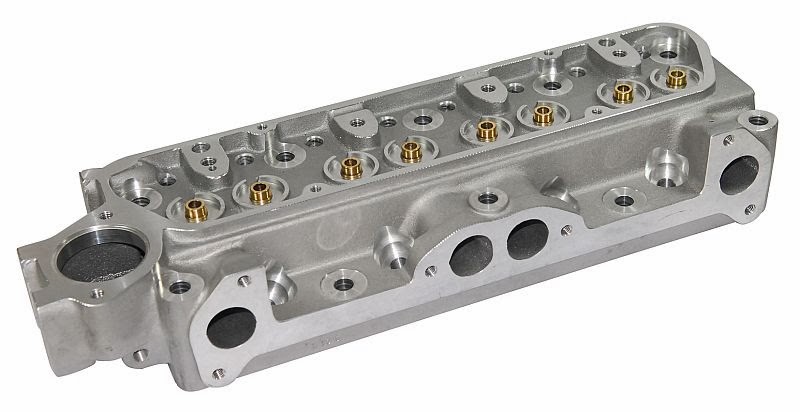
In comparison, the X-flow cylinderhead (aluminium):
The block came in different castings and heights, depending on capacity. The very beginning was made with a 997cc unit, up to 1600cc at the end of production. The latest blocks could be bored for larger capacity. It was and still is used in Formula Ford 1600, that’s why for some time it became difficult to find engine blocks. Production has been renewed since 2010 and you can buy new blocks (2).
The 1600 came as
2737e as seen in early Ford Cortina Mk II
681e … later Ford Cortina Mk II
691e … early Capris
711m … Capri, Cortina, Escort and a lot of Kitcars and small production cars,
plus the AX block as the toughest with some 5kg more on the scale, but with a better casting and suitable to be bored out even more. The cast engine code is visible below cylinders 1 and 2 on the exhaust side together with indications for capacity: 6015AA = 1300cc and 6015BA = 1600cc (3)
.
The most sought after engine block is the 711 with a better casting. The AX is quite rare. You can rise the capacity and use oversized pistons, cast or forged. The word goes you should not exceed 1700cc and 6800RPM, but you may come across larger figures. Although, life expectancy is largely compromised and there are other engine configurations more suitable.
The common 1600 out of a Cortina MkII had 84hp with a single carburettor. Depending on tuning, power rises as you add larger valves, sharp camshafts, higher compression, bigger double carbs a.s.o. Kent engines have been supercharged or turbocharged.
It is very common to find good road-going mildly tuned engines with 120-135hp. For more power, you really have to do a lot of work and apply steel components and Accralite pistons to make it work. Personally, I wanted to try the injection route and added individual throttle bodies to a reasonably tuned engine.
There are companies specialised in tuning this engine and it is a matter of money how fast you want to go. A lot of home-built engines show that it can be done in a private workshop as well. Parts are largely available with an engine having been built by millions over several decades. On this website (4), you can see what Cosworth did to it and how this engine has been the basis for a lot of sports- and racecar engines. For quite an extensive web article about Cosworth engines, read on:  http://www.italian.sakura.ne.jp/bad_toys/cosworth/
Further development led to single overhead (SCA) and double overhead (BDA and following) camshafts, geardriven or by belt.  
As this is all still based on the Kent engine, but with quite a big development work behind, I will stop it here and the next post will be about the cylinderhead.
Sources

3) Casting Numbers
4) Cosworth (by Sakura)
5) Burton (parts and more)
6) Wilcox (parts) 
7) Article
8) Article
9) Article
10) Story

Tuesday, November 12, 2013

Brake circuit design (without math)

Warning! Don’t touch your brakes unless you know what you are doing. As with other safety relevant components in your car (steering, suspension a.s.o.) your life depends on it. What I describe in the following is about my car. You may find information suitable for your application, but I can in no way be made responsible for anything happening to you,  your car or anybody (anything included) getting in your way as you drive, brake or trying to.


Components list
Front:  HiSpec 4 piston aluminium brake calipers, M16 bolt pattern, ventilated discs 245x20mm
Rear: standard Ford 9” drums
Pedalbox: highly modified OBP
MC’s: Girling type (see text for diameters)
Fluid reservoirs: Aluminium with level sensor
Fluid: ATE DOT4
Tubing: Cunifer
Flaring-tools: K-tools


My car had hanging pedals from stock. I went to floor mounted pedals during the rebuild and redesigned most of the braking system. Although you could do this with mathematics, starting from caliper diameters over pedal ratios and needed volume, I had some of the components already in place and had to adapt everything around. Anyway, the brake pedal now operates two separate master cylinders for the front and rear brakes, I stayed with the cable operated clutch. The pedalbox has been purchased from rallynuts.com


This particular model has a square recess where a chassis rail is present in most kitcars. Thus, it can easily be adapted. Although it is intended to be floor-mount, I welded brackets on to the chassis for a secure fixing. The kit comprises a bias bar, brake fluid reservoirs, hoses and two master cylinders (MC):
- diameter 0.700 intended for rear brake circuit
- diameter 0.625 intended for front brake circuit
As my particular set-up showed, those values are not applicable for me. Both MC’s are too spongy for the front circuit and pedal travel therefore is too long. The pedal even hits the bulkhead. The smaller MC is all too big for the rear circuit which results in a very hard pedal. Further on, I will check whether I will insert a pressure relieve valve to accommodate with the rear brakes.

Assembly  
For some reason, and I can only guess it is because of safety matters, manufacturers and resellers of brake components don’t give a lot of information about the assembly and set-up of their products. Maybe they prefer professionals to do those installations to prevent us amateurs fiddling around. On the other hand, the more good information I have, the better and safer my modifications will be.

The first problem I encountered was how to assemble the bias bar. It is not obvious, at least not for me, how to do it, unless somebody tells you. The clevis is mounted first, and then the master cylinder’s pushrod is bolt on. This rod can rotate, if you have enough space, you can rotate the whole MC to bolt it to the clevis (prior to plumbing). If you mount the clevis to the MC’s pushrod prior to fit it to the bias bar, it is impossible to mount them both. As soon as you screw in the second clevis, the first one is screwed out. Sounds funny? It is!
Above diagram shows how to align everything to start, further settings will show alterations.
After that, you have to be familiar with the function of that bias bar. I found a very good explanation in a UK forum http://www.locostbuilders.co.uk/viewthread.php?tid=171423 . Hopefully this thread will be reachable with above URL forever.
This diagram explains how it works, but … you must know that while pushing the brake pedal, you start braking on one MC, which then becomes the pivot point together with the big internal olive of the bias bar. Only then force is applied to the second MC and the braking process goes on. Now you can set up the system to suit your driving or legal regulation i.e. the front brakes should lock before the rears. In above you can see that the front MC pushrod is not as deeply bolt into the clevis as the rear MC.

Design
The front brakes need more fluid for operation since the brake pistons are of a larger diameter. This means that the front MC needs more travel for a given MC diameter. There are some possibilities to achieve this:
- set the bias bar askew as of start of pedal movement (see above 'no pedal effort'-position)

- shorten one of the pushrods (not recommended)
- put a spacer under one of the MC’s to put it away from the bias bar (see below)
To start the design for my car, I had the following set-up with the new pedalbox:
The approximate pedal travel of 124mm must suffice to activate the front brake until block and even leave some place before hitting the bulkhead, which leads to problem number 1:
- the 0.625 MC intended for front brakes needs too much travel and the pedal hits the bulkhead
- the 0.700 MC intended for rear brakes used up front for trial wasn’t big enough either
 
Solutions
- order a 0.750 MC and try (order placed March 5, 2013, arrived March 12,2013)
- alter the pedal ratio or bring it nearer to the driver, both need major mechanical alterations (will do if no success with above solution)
Possibilities to reduce distance between pedal and bias bar / MC and bias bar:
 - Put in washer when mounting MC
 - Shorten pushrod
 - Screw pushrod further into clevis
 - Manufacture specific clevis

Further design is only feasible once problem no.1 (pedal hitting the bulkhead) has been solved.

Some TEE (trial and error engineering) to follow...
2013 03 18  
Yesterday, we put in the 0.750 for the front brake circuit and the 0.625 for the rear. The pivot is set completely to the left side (front brake). Problem no.1 is solved, the pedal not hitting the bulkhead anymore. After bleeding both circuits, it is not obvious that braking is ok because pedal travel is reduced by the whole setup and I don’t know if the front brakes get activated enough for a full stop or block.
Next thing to do: try to further reduce pushrod length off the rear MC (bolt it further into clevis). I have to design a little tool to grip the pin holding the protective sleeve and turn the pushrod. I will turn it into the clevis as far as possible without blocking the bias bar movement (tonight). Next option will be to recess the rear MC mounting.
Pedal travel is around 100mm for now. With a ratio of 5:1, this gives 20mm piston travel (max is 25mm). 
I measured the piston travel from rest to fully applied and found 25mm (1” … ?).
2013 03 20  
Thoughts …
The pushrod of the rear MC was already bolt in at its max, no further setting possible.
Next weekend, I want to assemble the car for roll out and do some testing outside. Therefore I need to mount the scuttle and plumb the water circuit ready, fasten the suspension bolts once the car rests on its wheels, and maybe some other smaller jobs.

2013 03 23  
Short roll out with 0.750 front and 0.625 rear, I can block the front wheels but haven’t seen if the rears block first, second or if they block at all. Next time I will have Max or Pit (or both) to watch the wheels. Ideally, it is possible to do the fine setting. Pedal feel is quite ok and I look forward to the final setup. 
2013 09 20 (engine rebuild in between)  
Pedal feel is quite hard for full stop, but ok for normal operation.
Car passed MoT (SNCT-Sandweiler). Note that for some technical controls (depending on countries), the bias bar has to be blocked and dash mounted knobs permitting bias adjust on the fly are prohibited.

In conclusion
Although my approach was far from being scientific, I managed to design the brake circuit to operate the already existing braking gear. Selection of MC’s was by trial and error (and some swearing), but one should be able to resell what isn’t needed or keep it for other projects. At the time of construction, universal Girling style MC’s cost around 25.-£. Click labels at the end of this post to see more about braking on this blog.
Cheers.

Wednesday, October 9, 2013

Electronic Control Unit - ECU

With one post listing the market's throttle bodies, it was obvious to follow with a round-up of ECUs. There is a wild bunch out there and I had to limit myself with some criteria. The two main topics for me are "free programming" and "universal use". You can find ECUs allowing to be tuned only by professionals or freely tunable ones but for specific engines only, as well as motorcycle, ATV, snowmobile or watersports specific ECUs ... those are not in my list. 
Megasquirt is the most popular DIY controller, you can even solder it yourself if you dare. I avoided its derivatives as they are all based on the same board. Nevertheless, the following round-up may not be complete, so if you know of any other brand, feel free to add a comment. Brand names are links (please report dead links).
Cheers.

AEM - Bosch - Canems - DTA - ECUmaster - Emerald - EMS - Haltech - KMS - Magneti-Marelli - MBE - Megasquirt - Motec - Omex - Perfect Power - Sybele - Trijekt - Weber - ...

Wednesday, October 2, 2013

Throttle bodies

Although the conversion is made and functions well, I wanted to have a look at what other throttle bodies I could have used. Quite rapidly, I decided for Jenvey because they have a good reputation and were included in a kit I purchased. One of the main criteria was the bolt on ease due to the Weber DCOE and/or Dellorto DHLA bolt pattern. The manifold can be maintained if you had such carburettors beforehand. I limited the search for other brands to those which have DCOE-style throttle bodies, but also found a lot of DIY items, ranging from the welded injector bung in the manifold to the complete engineering, milling, turning and manufacturing. So here comes the round-up! Feel free to drop me a message if you know of any other brand manufacturing their own design. I will be more than happy to add them to the display.
Cheers.
(clicking on the name leads to the manufacturer if available, updated February 5, 2014)

ALPINA
(well, if you want to have something special, theseTBs also sport the Weber bolt pattern... and with the original red trumpets, it just looks the lot :-)... as found on Alpina 2002tii (B4) f.ex.


AT


DBILAS


Saturday, September 21, 2013

MoT - yeeeeeaaaaah!

Finally, after a two years rebuild, my car is officially on the road again. This is the first weekend since October 2011 that I will not work on the car... peacefully resting in its home again.
Cheers.

Sunday, September 15, 2013

Still not RTR (Ready To Race)

Some more small problems to struggle with that make that I still have no MoT. The small one was a loose bolt on the diff carrier (solved after a dive underneath the car), the complicated one was CO being too high and the labour intensive one was a cabling error to the headlights. I did a mess and mixed up ground with one of the headlight 12V+ wires. Silly me! Solved whilst resoldering, followed by adjustment.
The technical control mentioned a CO rate of around 8% which is far too high. During TechnoClassica in April I purchased a Gunson Gastester. Out it came to try adjustment on my own. Here is how I proceeded:
- run the car so it is hot (around 80° water T)
- connect the gastester and leave it for 8min
- calibrate the gastester to 2% and wait another 2min to let it stabilize
- put the probe into the exhaust and leave it there until you get a reading
- open the map in your ECU and go to the live adjustments (Emerald)
- tap 2 to decrease or 3 to increase fuel (injection trim)
Before you start, be sure to adjust iddle and check the TPS (throttle position sensor) setting.
I managed to set it to 1.6% which should be ok, than had a run and checked the value. It was slightly higher but still ok. I may repeat the adjustment just before I go to MoT next time.
Cheers.

Tuesday, September 3, 2013

NGK BPR7ES

Thats the type of spark plugs I now use!
Previously I ran the same type without the R (BP7ES) and it was fine with carbs. Now that I converted to injection, these no longer work. The difference is quite spectacular: rough idle, idle remains not constant when warming the engine, bad combustion a.o. After I rebuilt the engine it ran ok but had some backfire on idle when warm. Checking with Dave Walker, head of Emerald ECU, he recommended to use the "R" plugs. Now the engine runs a charm ... fingers crossed it will do for a long time.
This is mostly due to RFI (radio frequency interference) generated together with the spark. No harm for carbs, but as soon as electronics are involved, it matters.
Gap is set to 1mm. Have a look at above chart if you travel through both imperial and metrical worlds.
Once the engine is run in, I will do a power blat and check the spark plugs colour. Only then I will proceed to more tweeking of the ECU settings (ignition and fueling).
Cheers.

Sunday, August 18, 2013

Saturday, August 17, 2013

Running again

With the head back on, I started to set the valves. This means turning the crankshaft until one valve of a cylinder opens completely, then set the one that is supposed to be closed. Here is some data I collected about the values and different procedures. After that, I bolted the injection back on.
Engine temp: cold
GT (standard)
Inlet: 0.28-0.33mm (0.20-0.25mm)
Outlet: 0.53-0.58mm (0.46-0.50mm)

Data from Vulcan Engines for a Kent 290 camshaft
in: 0.36mm
out: 0.46mm

Method “by cylinder”
When one valve is fully open, adjust the clearance on the other.

Method “rule by nine”
if 1 and 6 open – set 8 and 3
if 4 and 2 open – set 5 and 7
if 8 and 3 open – set 1 and 6
if 5 and 7 open – set 4 and 2
Firing order = 1-2-4-3 (1 is opposite from flywheel)
Order of valves from cylinder one (I = inlet; O = outlet):  I-O-O-I-I-O-O-I
As soon as it revved (filling coolant and oil first!), I checked the ignition advance with the strobe light, oil pressure was ok. But I will also check all the other settings before driving it again.
Cheers.

Tuesday, August 13, 2013

Biiiig exhaust gaskets

Compared with the normal gaskets between the exhaust manifold and the cylinderhead, those from Vulcan Engines are five times fatter. The other thing they do different is the fixing. Whereas originally stud bolts come out of from the head, the manifold is now fixed with Allen head bolts. Except for one (middle right) which I had to change for a hex head due to limited access.
Prior to assembly I recut the threads to prevent the new bolts from biting too much into the head.
Cheers.