What you will find here: Intended to display minor modifications to my Westfield SEi, this blog now witnesses the two year rebuild (and more) after a major crash in October 2011. Have fun and feel free to add a comment at the end of any post.
Best viewed with Firefox

Pages

Thursday, November 22, 2012

Lucas ACR Alternator

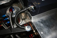
A good connection of the alternator is essential. Contacts and terminals should be ok, cable cross-section big enough. The Lucas ACR alternator has a black 3pin cap. Mine has lost it's cover since long, the brown cable got stiff over the years and I wanted to improve the whole charging circuit. The diagram shows the original cabling with two 2.5sq/mm to connect to the battery and starter. I opted for a 6.0sq/mm section which gives a little more cross-section and only one cable to install. I soldered it to the brown cables very near to the connector.
The case is ground and connects the negative to the battery and starter via the chassis. The positive spades are 9.5mm (ref. T407) for the charge current and 6.3mm (ref. T406) for the warning light on the dashboard. Click the terminals' pic to get to a complete guide of all the automotive terminals and connectors.
Cheers.

Wednesday, November 21, 2012

Sensor harness

After identifying what goes where, I split the ignition/injection-harness into two parts: one going to the engine bay connecting to all the different sensors and one going to the fuse-box.
Silly enough, some of the mods already have to be modified. Velcro straps are not allowed to hold a battery. The bracket has to hold back the battery during a crash, so this is one for a Varley red top battery of the same size. Brake fluid reservoirs have to be transparent, alternatively there must be a level indicator. I have to find a way to adapt the cap on the right reservoir to the kind of cover shown on the left one.
Winter can come now with this little fella at my side (3300W).
Cheers.

Sunday, November 11, 2012

Connections


The goal is to hide electrics as much as possible. Front and rear looms are in, the ignition/injection loom has to be done. Some devices are already connected and can be checked (horn, fan), others have to wait (pump, lights). Small additional looms will connect the lights and flashers.
This opening will be hidden by the fuse/relay-box and connect to the different looms. The Emerald-loom stays separate.
Cheers.

Thursday, November 8, 2012

Today, around noon ...

Impressive! Thanks a lot. A little bit more than a year has passed since start. The car is not finished yet, but should be for spring 2013 (fingers crossed).
Cheers.

Sunday, November 4, 2012

What goes where?

Some more cabling done today, labels are important to know what goes where. Nice short battery ground to an upper chassis rail, especially where high currents flow, it's important to keep cables big and short.
Cheers.

Saturday, November 3, 2012

Battery strap

Don't want to loose it, so here's my plan ... only following the minimalist road with this simple velcro strap.
Cheers.

Thursday, November 1, 2012

Battery tray

A small battery only needs a minimalist tray. This one is made out of 25/25 aluminium profile, four corners bent and riveted to the panel. The inside is covered with fleece to prevent the battery from scuffing.
The battery then will be fixed with a velcro ribbon.
Cheers.

Monday, October 29, 2012

Emerald

Basically what it is about the Emerald is to connect everything you need for ignition and injection to a small computer. The wiring diagram above is for a distributorless ignition system. The manual for the whole system is available here. At first sight, it might look complicated, but you have to look at it part by part. As I progress with the wiring, I will try to explain the different components and what they are for.
Cheers.

Sunday, October 28, 2012

Electricity

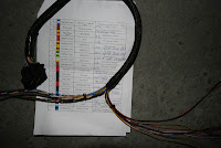
Most ungrateful job ever, lots of hours spent and to be spent, and all you can say is, well, flick this switch and the lights go on, push that button and the horn honks ... a.s.o. The Emerald ECU (Engine Control Unit) manages ignition and injection. A 36-way connector exits one side of the box and has to be connected to a large amount of sensors, relays, coils and injectors. The second pic shows the split harness with one side grouping all the sensors.
Starter motor is wired. Big plus goes to battery, second biggest comes from the alternator and goes to the battery (charging), third biggest commands the solenoid (starter relay).
Cheers.

Wednesday, October 24, 2012

Battery

Forums are usefull! Although I wanted to buy that blingbling racing battery (why? I don't even own a racing car!), I now opted for this humble black brick of energy. Technically it is about the same at less than half the price. It's a FIAMM FGH21803 12V 18Ah lead fleece type battery (12FGH65). It can be mounted at any angle and is used mainly in BMW motorcycles. A german forumist uses it since several years in his seven without any problem.
Cheers.

Sunday, October 21, 2012

Harness (start)

With the fusebox and ECU in place, I had to find the best spot to put (and hide) all the wiring. A large hole under the fusebox will channel almost all the cables from the main circuit. As far as possible, the harness for ignition and injection will be separate. Some edge protection prevents the cables from scrubbing thus avoiding unwanted stripping.
Cheers.

Saturday, October 20, 2012

Grounded

It's time to start with electrics. Cars in general and kitcars especially need a good ground. With a painted chassis and aluminium body panels, a good ground is essential for well functionning electric devices. The engine gets grounded via this copper loop with a paintless spot on the chassis. Some copper paste helps to have less electrical resistance.
Then some planning is required to achieve a neat cabling. I want to hide the wiring as much as possible. Not an easy task with all those sensors spread around the engine. The battery will be replaced by a racing gel battery from Odyssey, the oldfashioned Varta lump only serves as a place holder.
Cheers.

Sunday, October 14, 2012

Fuel swirl pot

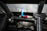
With a good start into plumbing yesterday, today I fitted two more lines. The pic shows the fuel swirl pot I will need when I convert from carburettors to injection. Four fittings shown from top to bottom:
- return fuel line, overflow goes back to the main tank in the boot
- from fuel pressure regulator, will be connected when the FPR is mounted
- arrival of fuel from low pressure pump in the boot
- this is where the high pressure pump sucks and delivers to the injectors
Cheers.

Saturday, October 13, 2012

Fuel lines

Ever fancied those plush red and blue fuel line unions? Me too! Together with braided steel hoses, they look good and give that little race car bling. But they are of high quality as well and you can manufacture them DIY. Here is how:
Cut the line with dedicated pincers, then put the screwcap into the Koul tool (more of this at the end of this post).
Now twist the braided hose into the screwcap until it shows just below the thread.
Put some lube on the thread and tape the spanner to protect the nice blue anodisation.
The finished line. Note the aluminium chuck jaws to prevent from dents. Pump connected.
Fuel tank 90° union and fuel return line aside the breather.
This is the aforementioned Koul tool. When cutting the braided steel hose, the sharp little wires are difficult to fit into the screwcaps. This tool helps a lot and keeps your fingers safe. The shown set contains inserts for D04, D06 and D08 dash size. Be sure to buy the right diameter hose along with the matching screwcaps.
Cheers.

Thursday, October 11, 2012

Surface finish

It's quite difficult to get a finish on new panels without making them look new on an old car. After 240 and 1200 sandpaper, I gave it a rub with grey scotchbrite. Although the result is matt, this process leaves some of the handling traces.
The (new) workshop watch should tell me when it is enough, shouldn't it?
Cheers.

Tuesday, October 9, 2012

Bulkhead

Cut and drilled a panel this evening to replace the bulkhead. The original panel had been riveted, but this one is bolted and can be removed to access the rear side of the dashboard. Recently I found quite a nice lid while recycling some stuff at work. I cut out where the steering column goes and adapted it to the bulkhead. This will be a nice and dry place for electrics with a rubber seal going all around it's bottom.
The lid is made of aluminium and I still have to find a solution to fix it to the panel underneath. The sign says: "This cover screw to be released before transporting by air" ... nice touch.
Cheers.

Aluminium cycle wings

Although this is only a project, I had the opportunity to buy some tools last weekend. There are different ways to DIY aluminium cycle wings and youtube gives quite a few hints, both amateur and professional. Some enthusiasts give their knowledge and publish it on dedicated sites like locostbuilders. That's where I found this tutorial (.pdf 412kB). My approach will be a mix of what I saw doing people here and there, but be patient, a lot of other things have to be done first.


Bead roller and 3 roller bending machine now in my workshop.
English wheel, maybe one of my next acquisitions, depends on success (or not) of the DIY route to aluminium cycle wings (and on budget of course).
Cheers.