What you will find here: Intended to display minor modifications to my Westfield SEi, this blog now witnesses the two year rebuild (and more) after a major crash in October 2011. Have fun and feel free to add a comment at the end of any post.
Best viewed with Firefox

Pages

Wednesday, April 11, 2012

Upper steering column & quick release


Quick release system LOCKED !
Quick release system UNLOCKED !
Quick release system RELEASED !
The lever is springloaded, the hex connector is welded to the steering column.
Prior to mount, the hex connector welded to the steering column and the upper bearing with two half bearing shelves. The connecting rod to join the hex part with the steering shaft was turned on a lathe and the bearing surface is now integrated.
The lower bearing made out of brass on the lathe.
Different bolt circles on steering wheel and quick release hub ask for an intermediate adaptor plate to bolt the steering wheel to the hub. Turned out of aluminium. 
The steering system is almost completely new and bespoke for my car. The selected heavy duty steel for the column parts and the newly designed bearings are a safe construction. The added quick release system might appear superfluous, but is a very useful goodie adding some more race feeling.
Cheers.
Saturday, April 7, 2012

Lower steering column

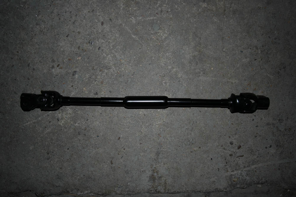
Lower steering column, shortened, welded, painted. Looks like bought.
It's a tight fit along the chassis rail, but there's enough room for the column to spin freely.
The upper coupling is quite near the exhaust manifold, but a less cramped fit than previously when I had to shave a little off of the coupling and shorten the bolt to it's minimum. Next will be the quick release hub for the steering wheel at the other end of the column.
Cheers.

Thursday, April 5, 2012

Steering column parts

With the exhaust manifold in place, the steering column can now be designed. The upper part is lengthened just enough to pass the manifold. I welded a new shaft onto the existing part with a 36 spline end to bolt to the coupling.
The lower part of the steering column joining the rack has to be shortened accordingly. Above pic shows from top to bottom
- the amount of length added compared to before
- the lower part of the column to be welded with a coupling at both ends
- the closure that will cover the weld and then will be welded additionally to further strengthen it.
One more goodie, although I've not yet decided wether I will mount it or not, this is a quick release system for the steering wheel. Two possible advantages of a removable steering wheel are ease of access (especially in a small car) and theft protection ... well, for the latter, the thief will have to bring his own.
Cheers.

Tuesday, April 3, 2012

Water cooler

The (new) Caterham water cooler is very lightweight. It is mounted through vibration dampers to the chassis. The old water cooler was damaged beyond repair during the crash.
The Samco piping can be reused which makes for some money saving.
The Pacet fan was broken as well and has been replaced by exactly the same item purchased together with the water cooler. Luckily I kept the wrecked fan and now reused the clips to fix it to the cooler (no clips provided). The overflow will be connected when the bulkhead is ready to receive the expansion tank.
Cheers.

Monday, April 2, 2012

Pedalbox completed

Hours and hours spent, the last change adopted was to alter the pivot center of the clutch pedal. Things went fine with sheet supports bolted to the pedalbox chassis...
... and some more sheet welded to the lower lever of the clutch pedal to fix the clutch cable. The foot rest is adjusted to its lowest point. The final adjustment of all three pedals will be done later (clutch and accelerator when the engine is running, brake pedal when the piping has been completed).
Cheers.
Jos

Sunday, April 1, 2012

Scale models (will be updated)

What kids buy their father ... especially if his limited mind only turns around cars of a special kind:
- Kyosho Caterham Super Seven (cycle fender) #08222SC (scale 1:18)
- Kyosho Caterham Super Seven JPE #08225C
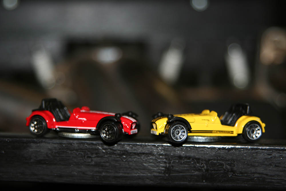
Little souvenirs from our trip to Dartford December 2011 (scale 1:64):
- Matchbox 2011 #03/75 CATERHAM R500 SUPERLIGHT (available in yellow and red)
Streetsale in Faversham May 2012 (scale 1:64):
- Matchbox 2011 #111/120 CATERHAM R500 SUPERLIGHT (black, yellow stripes, silver cycle wings)
June 2012, toys shop, Luxembourg
- Kyosho 1:43 CATERHAM SUPER SEVEN JPE (Silver Carbon) No. 03156C

More to come ...
Cheers.

Thursday, March 29, 2012

Clutch pedal modification plan

The original clutch pedal will not give enough travel to operate the clutch. As I want to keep the pedal as it is, the mod will be bolt/riveted to the existing installation. Therefore, the lower lever will be extended and the pivot center mounted higher (approx. 15mm). The upper lever will be shortened accordingly.
This is how the higher pivot center should look. With 60/190mm the ratio will be 3,16 (previously 4,77). Hopefully, this will accord with the required clutch-fork travel and give a good pedal feel when driving and changing gears.
Cheers.

Wednesday, March 28, 2012

News up front

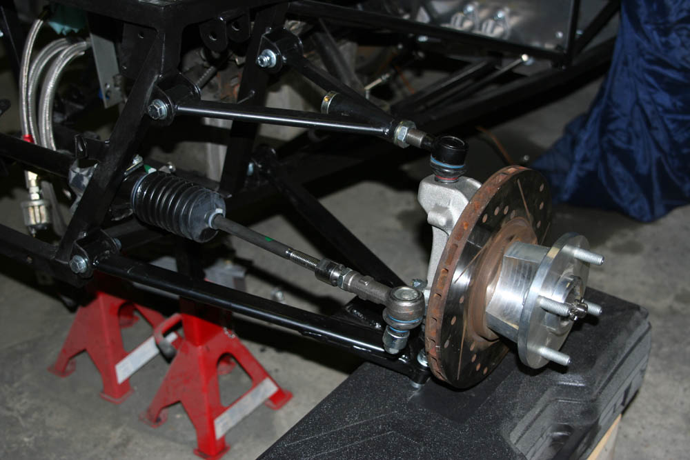
New steeringrack mounted up front. Looks posh with those big aluminium brackets.
Front left suspension with wheelcarrier and hub and discbrake. This is only for trial, the body panel has to be fitted first for the final assembly.
And some more homework ... the clutch pedal from OBP has not the right ratio. I have the choice, modifying the existing pedal or designing a new one. Depending on available time (and skills), I will decide. I'm tempted to build a pedal which will exactly suit my needs and keep the original pedal in case I need it anyhow.
Cheers.

Monday, March 26, 2012

Assembly progress

Lovely little budget pipe bender and a little test with 8mm aluminium fuel pipe. The result ist quite ok. On the left, some homework to be done on the handbrake adjuster. It must be shortened due to the new location of the handbrake.
Some assembly work done tonight, rear brake pipes (to be bend in place) and handbrake cables, the Westfield differential which is basically Ford Atlas gear inside a bespoke Westfield differential housing.
Driveshaft is a Caterham part in this particular car (part# 72290) to connect the Ford T9 gearbox with the differential.
Diff and driveshaft and brake piping.
Rear suspension with upper and lower wishbone, half shaft and shock absorber.
Quite satisfied with tonight's assembly work, at least it appears like some progress achieved. More time will be lost in details like the handbrake adjuster and pedalbox which is still not completely finished. The brake pipes will then be mounted properly and the fuel pipes bend to the chassis's profile.
Cheers.

Thursday, March 22, 2012

Size matters

Long versus short. The clutch cable in the car was rather long. The short one is from a Ford Escort MkII and will be a better fit. In case you encountered a similar problem, try to get the clutch cable with the Ford part# 15613600 from a 75-80 Ford Escort (talking about the 20th century!).
 
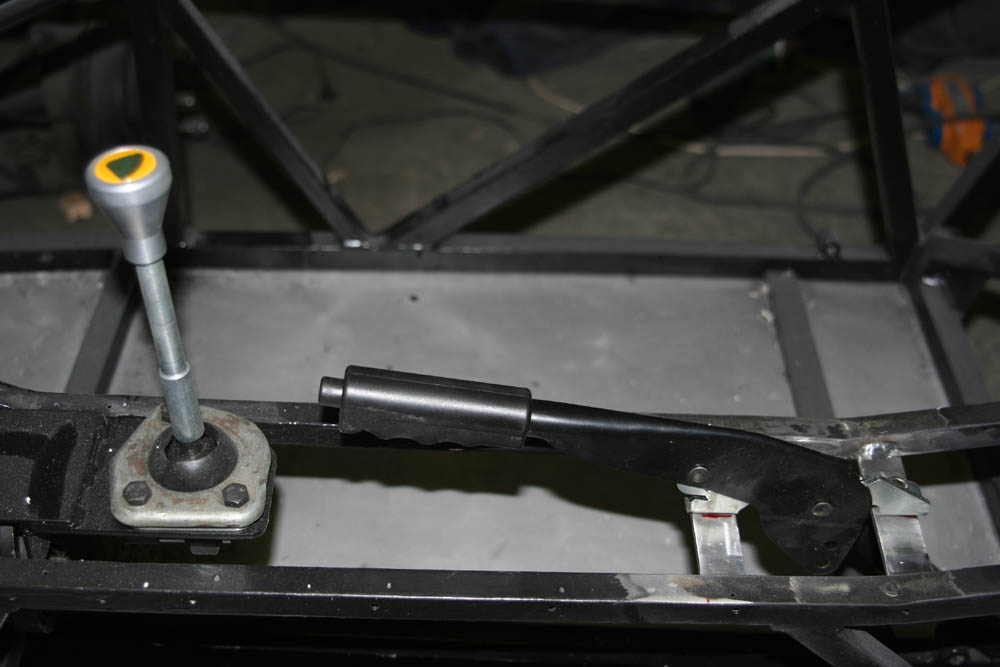
The handbrake lever positioned further back will not interfere with the gearlever anymore. I'm quite pleased with this disposition. Hopefully, I will find a good way to clothe both levers and make it look like a well designed car from the inside as well.
Cheers.

Wednesday, March 21, 2012

Always work and no play makes Jack ...

24th Techno-Classica Essen / Germany  from 21st to 25th March 2012.
THE exhibition not to be missed if you're a fan of classic automobiles.
I'll be there on Friday 23rd to buy some stuff for my car and admire all those fantastic cars, motorcycles and accessories. It's an overwhelming fair both in extent and in quality.
Cheers.

Monday, March 19, 2012

The never ending change

Yeah, tonight I want to put the new handbrake lever into the car ... well, that's what I thought. After I put the gearlever with it's extension, it became obvious that they interfere.
Before cutting, welding and painting once again, this time to reposition the handbrake lever, I allowed myself for some trial seating to check for the new gearlever position. Perfect! Later I will cut the lever to the most practical length. The extension works fine, but I have to check for the reverse protection.
The well known history ... I already cut out the old brackets, prepared some steel and marked the chassis. Welding is next, then drilling and painting the altered chassis section. Recurring gestures.
Cheers.

Water cooling circuit

As assembly progresses (well, sort of), some theory worse to be spread about the plumbing. Let's start with the water cooling circuit. Starting with a layout lent in a german forum, I adapted it to what will be found in my car once completed (ex the water temperature gauge which will be integrated into the digital Stack dash). Quite a basic setup without a heater, hence the missing pipes and valves. Note the two separate temperature sensors, one for the stack gauge and one for the Emerald ECU. There are two ways to switch the fan once a set temperature has been reached:
1) via the temperature switch (mechanical / bi-metal) in the thermostat housing, fixed value
or
2) via the ECU where the switching temperature can be set as wished.
Cheers.

Saturday, March 17, 2012

... and more brackets!

A rebuild is a chance to do things better. One annoying missing feature was a rest-pedal for the clutch foot during long journeys. Out of aftermarket aluminium pedals I cut two small pedals and mounted the larger one. If it appears to be too large, I will mount the smaller one. A small bracket welded to the chassis holds the pedal.
The high pressure pump for the fuel injection conversion will be mounted near the swirlpot and underneath the throttle-bodies. A little bit of steel is needed to fabricate a bespoke bracket.
 Bracket welded in place and holding the HP pump for trial fit.
Top view to show how the HP pump will connect to the swirlpot. The pump will almost not be visible once the throttle-bodies are in mounted.
Cheers.

Sunday, March 11, 2012

Swirlpot

The fuel injection system will need a swirl pot. But where to put it in such a small car? After a first attempt to install everything in the boot, the rebuild allows for some other ideas. Starting with the purpose built bracket early this Sunday morning ...
... and the swirlpot mounted. Now the ideal spot for the high pressure fuel pump can be found and another steel bracket will be welded to the frame as this device is quite heavy.
A little bit of theory about the plumbing of a swirlpot in a fuel injection system from SBD. Modern fuel injected cars have the swirlpot integrated in the tank. In a car originally not equipped with EFI, a swirlpot has to be fitted separately to avoid fuel failure due to surge in fast corners.
Cheers.

Thursday, March 8, 2012

Pedalcar

The clutch cable routing shows that the cable is quite long. Connecting it to the pedal is not complicated and there is enough remaining cable for adjustment. I wanted to keep the clutch cable operated and not add a piston and convert to hydraulic.
The pedals mounted with the throttle operation finished, the clutch pedal to be adjusted and the brake pedal to be modified. I decided to alter the original adjustment system for ease of use. With all three pedals in place, it is possible to choose a spot for the footrest destined for the clutch-foot. Not much room left, but I really want to try fitting one for comfort during long journeys.
Cheers.

Monday, March 5, 2012

Cleckos

Funny name. Another one could have been "provisory rivets". This would have explained the function as well. A spring loaded inner mechanism expands with the special tool pictured. Then the clecko is fixed and the spring released.
One pic instead of thousand words, a few cleckos help to provisorily fix the panel. Than I can mark the big holes for the brake master cylinders and cut them out.
As soon as the panel is fixed, the brake master cylinders can be mounted. For good.
Backside of the pedalbox prior to mount the pedals. Throttle and brake linkage are solved, a solution for the clutch activation has to be invented yet. But this is basic mechanics and feasable (hopefully...).
Cheers.

Thursday, March 1, 2012

Repro

Not the best workshop session tonight because I'm not completely satisfied with my work. Half way through, it became obvious that the reproduced new panel will not enter the frame with the engine already mounted. Two possibilities:
#1 engine out - panel in - engine in
#2 cutting the panel into two pieces
As it will almost not be visible, I opted for solution #2. It would have been nice to have that panel in one piece, but the amount of work would have been immense. Heat shield will cover the cut.
Split panel in place with Sicaflex for sealing and fixing, 4x12mm rivets with large heads. Imagine some heat shield on it and the swirl pot fuel tank mounted. A.s.a.p. I will add a pic with the panel in focus.
Cheers.